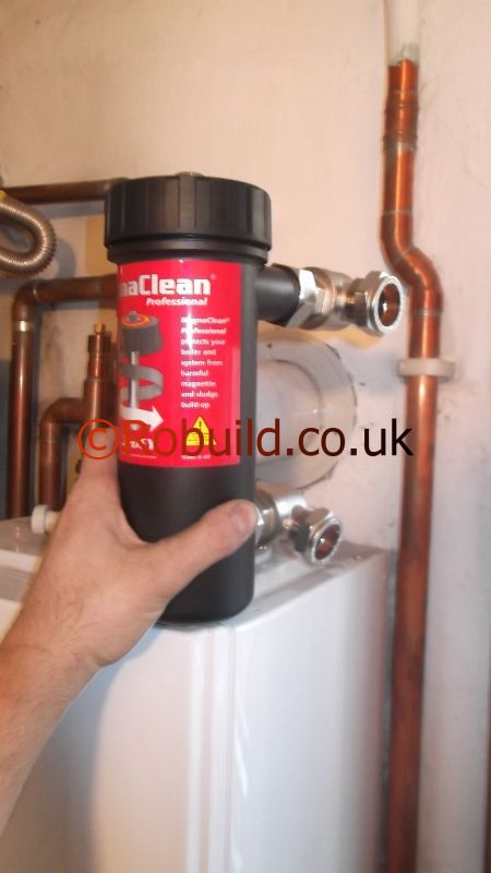
Boxing in pipes

Plumbing means pipes, which can be unsightly if left exposed. Boxing them in will tidy up the look of the home. Whichever method you choose to conceal pipes, the first task is to strip the wall around the pipes so a supporting frame can be securely fixed. Make sure the pipes are in good condition and that the joints are well made. Check compression joints for tightness and, if there is any corrosion, remake the joints. Before boxing in make sure the pipes are fixed securely to the wall with pipe clips.
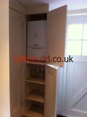
boxed in pipes & boiler
Boiler boxed in – cupboard

Where pipes come through the floor from a room below, seal the gap between the pipes and the floor with a shaped piece of 12 or l8mm chipboard to reduce the risk of fire spreading. Pipes on an outside wall should be insulated with a glass fibre blanket or with shaped foam secured with tape.

Making the box
Using plugs and screws fix 25 x 19mm timber battens vertically to the wall on each side of the pipes; check with a plumb line to ensure accurate positioning. Where the pipes are on an open wall, glue and screw or pin 12mm thick plywood or chipboard to the sides of the battens (the width of the timber side pieces depends on the depth required for the box). Where the pipes are in a corner you will need only one side piece and, if the pipes protrude less than 50mm from the wall, you may not need side pieces at all. In this case use 25mm battens, wide enough to clear the pipes, as side pieces.

Front panel
Cover the pipes with 3 or 5mm hardboard or plywood; if you want a more solid panel, use 12mm chipboard. Don’t glue the front panels in place because you must have access to the pipes in case of leaks. Fix hardboard or plywood with panel or hardboard pins and secure chipboard with countersunk screws. You will achieve a better finish if you cut your front panel slightly oversize and trim it back with a plane once it is fixed in position. Use a cellulose filler to fill any cracks and countersunk screw heads, except where these provide access. Give the box a coat of primer before decorating as required. When decorating, make sure you do not cover the join or your decorations will be spoiled when you need to remove the box.

Stopcocks and draincocks
Where there are stopcocks or draincocks in the pipe runs you must cut holes in the front panel to allow the handles to protrude, unless you fit access covers in the boxes. Alternatively construct a box which can be easily removed. Make up a hardboard box of the required size, using 25mm square battens at the front corners to give it form. On the inside face of the front panel glue 19mm wide battens at approximately 1m intervals and secure them with panel pins hammered through from the outside. Screw Terry clips of the required size, according to the pipe dimensions, to the battens; these will snap over the pipes and secure the panel.

Disappearing pipes
Where pipes disappear into a wall, the bottom or top (as applicable) of the box can be finished at an angle. Cut the side pieces and/or battens at 45 degrees, pin a small piece of hardboard or plywood to the sloping part and plane across the front panel until it forms a neat joint.

Alcove pipes
When you wish to conceal pipes in an alcove it is often best to cover the entire wall area with a full width panel; this robs you of little space and does not affect the look of the wall line. Fix timber battens on each side of the pipes, as previously explained. Plug and screw a piece of batten on each side of the alcove level with the front of the battens on each side of the pipes. Use 9mm ($in) chipboard, fixed with countersunk screws, to conceal the pipes and to provide easy access and nail 9.5mm plasterboard either side of the chipboard.
You can use the same method, but with a stronger framework, to conceal cisterns and soil and water pipes.

Skirting board pipes

Screw a batten to the floor with its face just in front of the maximum projection of the pipes. Glue and screw a 12mm facing board to the batten, then glue and nail scotia moulding to the top of the facing board. Finally glue and pin a strip of hardboard or plywood between the moulding and the top of the skirting. If you want a round edge finish, use a facing board of the same height as the skirting; glue and pin a length of 12mm board to the top of the facing board and skirting and round the front edge with a plane. Although a certain amount of time, effort and money is involved, you will be surprised how much neater rooms will look when the pipes have been boxed in. You can paint or wallpaper the covering.

Dealing with frozen pipes

winter london snow
If, in spite of your precautions, a freeze-up does occur, it is essential to deal with it immediately. If there is any delay the plug of ice will spread along the pipe and increase the risk of damage. You can gauge the position of the freeze-up from the situation of the plumbing fittings which have stopped working. If, for instance, water is not flowing into the main cold water storage cistern but is running from the cold tap over the kitchen sink. the plug of ice must be in the rising main between the branch to the kitchen sink and the cistern. Strip off the lagging from the affected pipe and apply heat – either with cloths soaked in hot water and wrung dry or a filled hot water bottle. If a pipe is inaccessible direct a jet of warm air towards it from a hair dryer or the outlet of a vacuum cleaner. Fortunately copper tubing conducts very well and a small plug of ice can often be melted by applying heat to the pipe about a metre from the actual location of the ice.

Burst pipe
If the freeze-up results in a burst pipe the first indication will probably be water dripping through a ceiling, since pipes in the loft are most likely to burst; wherever the leak, immediate action is vital. Turn off the main stopcock and open up every tap in the house. This will drain the cistern and pipes and reduce the damage. When the system is completely drained,find the position of the leak.

Damaged copper piping
If you have copper piping, you will probably find a compression or soldered capillary joint will have been forced open by the expansion of ice. All you need to do in this case is fit a new joint. Copper piping does sometimes split under pressure. If that happens, you will have to cut out the defective length and insert a new length. An easy way of doing this is to insert a repair coupling. Cut out the damaged section of pipe with a fine tooth hacksaw leaving a gap of not more than 89mm between the pipe ends. Remove the burr from the tube ends with a small file. One end of the coupling has a tube stop, the other is free to slide along the pipe. Slacken the nuts of the coupling, spring one end of the pipe out just enough to allow you to slide the repair coupling over it. Line it up with the other pipe end and push the coupling on to it until the tube stop is reached. Unscrew the nuts and slide them and the copper jointing rings along the pipe. Apply jointing compound or gloss paint into the bevels of the fitting and around the leading edge of the jointing rings. Tighten the nuts with a spanner so the tube is lightly gripped; make another turn, or a turn and a quarter, making sure you do not overtighten.

Burst lead pipe
The orthodox and approved of copper pipe and fitting method of repairing a burst lead pipe is to cut out repair coupling. Making the affected length and replace it with a new length temporary repair to lead pipe of pipe; this job is best left to an expert plumber. You can,however,make a temporary repair with one of the epoxy resin repair kits available. Dry the affected length of pipe thoroughly and knock the edges of the split together with a hammer. Rub down with abrasive paper. Make up the resin filler according to the manufacturer’s instructions and apply it round the pipe to cover the split and the surrounding area. While the filler is still plastic, bind round it with a glass fibre bandage and ‘butter’ a further layer of resin filler over the bandage. When thoroughly set, rub down with abrasive paper to make an unobtrusive joint. You will be able to use the pipe again within a few hours.

CoId weather protection

If the plumbing system in your home is not adequately protected, severe weather can cause water to freeze in the pipes, producing blockages and burst pipes. You can deal with these yourself, but it is better to prevent any damage by checking your anti-frost defences every autumn.

central heating boiler plumbing system

Protecting plumbing
Frost protection is built into the structure of a well designed, modern home and the important design points are explained be1ow.

Service pipe
This pipe conveys water from the water authority’s communication pipe to the house and should be covered by at least 750mm of earth throughout its length. If it enters the house by a hollow, boarded floor, it should be thoroughly protected from draughts. The pipe should be taken up into the roof space to supply the cold water storage cistern – against an external wall.

Storage cistern
The cold water storage cistern is best situated against a flue which is in constant use. To prevent icy draughts blowing up the warning pipe leading from the cistern. you can fit a hinged copper flap over the outlet; there is, however, a risk that this will jam in the open or closed position. A better method is to extend the pipe within the cistern and bend it over so its outlet is about 38mm below the surface of the water. There are gadgets, such as the frost guard, which make it easy to extend internally the warning pipe from a storage or flushing cistern. The boiler. hot water storage cylinder and cold water storage cistern are best installed in a vertical column so the vulnerable cold water cistern receives the benefit of the rising warm air. All lengths of water pipe within the roof space should be kept short and well away from the eaves.

Lagging
Efficient lagging of storage tanks and pipes reduces the rate at which water loses its warmth and protects pipes exposed to cold air; but it cannot make up for a bad plumbing design and it will not add heat to the system. Pipes to lag are those against external walls, under the ground floor and in the roof space. Don’t omit the vent pipe of the hot water system since the water in this pipe is not as hot as that in the rest of the system and, if it freezes, it can create a vacuum which could damage the cylinder. There are several types of pipe lagging available and it is best to use inorganic materials. These include wrap-round glass fibre; moulded polystyrene (which comes in rigid sections which fit round the pipe) and flexible moulded foam plastic (which you split open to fit round the pipe).

Polystyrene is rather awkward to use, but is good for underground pipes since it does not absorb water. The moulded types of lagging come in a variety of sizes to fit different pipes. so make sure you buy the appropriate size. Whichever type you use. make sure you lag behind pipes against external walls to protect them from the cold wall. Cover the tails of ball valves and all but the handles of stopcocks and gate valves; if you are using rigid lagging sections, you will need some of the wrap-round type for these areas. Bind wrap-round insulation round the pipe like a bandage, overlapping it to prevent gaps, and secure it with string or adhesive tape. Where a pipe joins a cistern, make a full turn and tie it to hold the end in place. When joining two lengths overlap and tie securely. If you lag the pipes before fitting them there is of course no need to slit the lagging: you can slide the pipe length through it. Where pipes go through a wall make sure the insulation goes right up the wall.

You also need to protect the cold water cistern. The easiest way to cover a square cistern is to use fire proof insulation slabs. For a circular cistern use glass fibre tank wrap. If you have insulating material between the floor joists in the loft, make sure the area immediately below the tank is left uncovered so warn air is allowed to reach the tank’

Protecting central heating systems

radiator modern
A form of electrolytic corrosion can take place in a central heating system where copper tubing is used in conjunction with pressed steel radiators. Some air – a prerequisite of corrosion – will always be present in the system; it dissolves into the surface of the water in the feed and expansion tank and may also enter through minute leaks too small to permit water to escape. Electrolytic corrosion within a central heating system results in the formation of black iron oxide sludge (magnetite) and hydrogen gas. This leads to impeded water flow and radiators will need continual venting to release airlocks to keep up the required heat level. The iron oxide sludge is drawn towards the magnetic field of the circulating pump and its abrasive qualities contribute towards early pump failure. Also the metal of the radiators, from which the magnetite and hydrogen are produced, becomes thinner until leaks eventually develop in the radiators. Removing airlocks by venting the radiator is a simple process. A key supplied for this purpose is inserted in the radiator when the water is warm and turned anti-clockwise to open the vent valve. Hold a container underneath the key since some water may escape when the valve is opened. Air will come out of the radiator – when it stops doing so and water begins to flow you should tighten the valve. If a radiator in your heating system needs to be continually vented, it is worth testing for internal corrosion while you are carrying out this operation. Apply a lighted taper to the gas escaping from the radiator; hydrogen gas burns with a blue flame and indicates the presence of corrosion.

powerflush central heating

Protection treatment
A chemical corrosion-proofer can be introduced into the feed and expansion tank to protect the system against corrosion. It is best to do this when the system is first installed, but it can be carried out with an existing system; it will not, however, undo damage already done. Before introducing a corrosion-proofer into an existing system you should get rid of any magnetite sludge with a special solvent. Like the corrosion-proofer, this is introduced into the feed and expansion tank and you should drain the system first. Disconnect the fuel supply to the boiler and switch off the ignition system several hours before draining to give the water time to cool. Tie up the ball float arm of the feed and expansion tank and fit a hose to the draincock near the boiler, running the hose to a drain outside. Undo the draincock empty the system and, when you have closed the draincock, free the ball float arm in the feed and expansion tank. Allow the system to refill, introducing the solvent at the same time. Follow the manufacturer’s instructions for the length of time you should allow for the solvent to complete its work before carrying out treatment with the corrosion-proofer.

Guarding against corrosion

corrosion power wash

Some plumbing fittings are subject to corrosion. When this occurs, they are weakened and eventually leaks develop. There are several ways of preventing this happening in your system. Modem galvanized steel water storage cisterns frequently show signs of rust within a few months of being installed. Older plumbing systems, which were constructed entirely of lead or galvanized steel, could generally be expected to last, without this kind of deterioration, for 50 years or more. In modern systems the use of copper, which itself virtually never corrodes, has greatly increased the risk of corrosion to any galvanized iron or steel fittings incorporated in the system. The process which gives rise to this corrosion is known as electrolytic action.

This is the same principle on which the simple electric battery cell is based; where rods of zinc and copper are in electrical contact with each other and are immersed in a weak acid solution which is able to conduct an electric current (an electrolyte), electricity will pass between the rods, bubbles of oxygen will be produced and the zinc rod will slowly dissolve away. A plumbing system in which copper water supply and distribution pipes are connected to a galvanized steel cold water storage cistern or hot water storage tank, may reproduce these conditions; the copper tubing and the zinc coating of the galvanized steel are in direct contact and the water in the cistern or tank, if very mildly acidic, will act as an electrolyte. This results in rapid failure of the protective galvanized coating allowing aerated water to penetrate to the vulnerable steel underneath; eventually rust will form. A particular form of electrolytic corrosion may result in damage to brass plumbing fittings, such as compression joints and stop valves. Brass is an alloy of copper. and zinc; electrolytic action may result in the zinc in the fittings dissolving away to leave them unchanged in appearance but totally without structural strength. Where these fittings in your plumbing system are showing signs of leakage, it would be worth checking with a local plumber if the type of water in your area is likely to create a situation favourable to electrolytic corrosion. If so, you should replace brass fittings with fittings made of gun-metal (an alloy of copper and tin), which is not susceptible to this kind of damage.

Corrosion as a result of electrolytic action is also likely to occur in pipework if a new length of copper tubing is fitted into an existing galvanized steel hot or cold water system. Always use stainless steel tubing instead – this is not liable to the same risk.

Protecting cisterns and tanks
There are steps you can take to prevent corrosion in galvanized steel cisterns and tanks. For example, when you are installing a new cistern or tank, it is important to make sure you remove every trace of metal dust or shaving resulting from drilling holes for tappings. The least fragment remaining will become a focus for corrosion. One way of protecting a cold water storage cistern is to ensure the metal of the cistern does not come into direct contact with the water it contains. This can be done by painting the internal surfaces with two coats of a taste and odour-free bituminous paint to prevent these surfaces from rusting. Before applying this treatment to a new tank, cut holes for the pipe connections: when you are painting. pay particular attention to the areas in the immediate vicinity of these holes.

Galvanized steel hot water storage tanks, which can still be found in many older homes, cannot be protected by this paint treatment.

Cathodic protection
A sacrificial magnesium anode which dissolves instead of the zinc coating will protect both galvanized steel cold water storage cisterns and hot water tanks. With a cold water storage cistern, clamp the copper wire attached to the anode to the side of the cistern using a G-clamp and suspend the wire over a timber batten into the water in the middle of the cistern. Make sure you replace the anode before it dissolves completely. When protecting a hot water tank, fit the anode to the hand-hole cover of the tank. Turn off the water supply and drain the system from the draincock beside the boiler; unscrew the bolts retaining the hand-hole cover and remove it. Drill a hole in the centre of the cover, use abrasive paper to rub down the area of metal around the hole and screw in the anode before replacing the cover.

Ball valves

Ball valves are vital parts of the plumbing system in the home, since they control the amount of water in your cold water storage and WC cisterns. They must operate efficiently, otherwise the cisterns will overflow – or not fill up correctly.

wc cistern ball valve

The purpose of the bail or float, valve is to maintain water at a constant level in cold water storage and WC flushing cisterns. All ball valves have a metal or plastic arm terminating in a float (not necessarily a ball) that rises or falls with the level of the water in the cistern. As the water level falls the movement of the float aim opens the valve to allow water to flow through it: as the level rises the arm closes the valve. The old types of ball valve the Croydon and the Portsmouth control the flow of water by a washered metal plug. The main disadvantage of these is that failure of the washer or dirt or corrosion on the parts can cause leaks. Modern ball valves, which have a rubber diaphragm instead of a washered plug, are designed to overcome these problems.

Croydon and Portsmouth valves
On both these valves a washered metal plug is forced tightly against the valve seating to prevent a flow of water when the cistern is full. The plug of a Croydon moves vertically within the valve body. When the valve is open, water splashes into the cistern via two channels built into either side of the body of the valve. Croydon valves are always noisy in action and, for this reason, are now rarely, if ever, installed in homes.

The Portsmouth valve is the one now most likely to be found in installations, particularly new ones. Its plug moves horizontally within the valve body and the end of the float arm is bent over to fit within a slot built into the plug. The noise of these valves used to be reduced by fitting a silencer tube into the valve outlet. This is a plastic or metal tube that delivers incoming water below the level of the water already in the cistern; it eliminates splashing and reduces the ripple formation that is a common cause of noise and vibration in ball valves. Unfortunately water authorities no longer permit the use of these silencer tubes, since in the event of water pressure failure they could cause water from storage and flushing cisterns to siphon back into the main.

Dealing with leaks
A steady drip from the cistern’s warning pipe indicates a worn washer a common fault on the Croydon and Portsmouth valves. It may be possible to cure the leak, at least temporarily, without changing the washer simply by lowering the level of the water in the cistern. There is no need to cut off the water supply to do this: remove the cover from the cistern, unscrew and remove the float from the end of the float arm. Take the arm firmly in both hands and bend the float end downwards, then reassemble. This will keep the water below the normal level, which is about 25mm below the warning pipe in a cold water storage cistern and l3mm below the warning pipe in a flushing cistern. (If you need to raise the water level in a cistern, bend up the float end of the arm.)

Changing the washer
If lowering the level of the water does not cure the leak, you will need to change the ball valve washer. First cut off the water supply at the nearest stopcock. Some Portsmouth valves have a screw-on cap at the end of the valve body: this must be removed. Straighten and pul1 out the split pin on which the float arm pivots and remove the float arm; insert the blade of a screwdriver in the slot in the base of the valve body from which the float arm has been removed and push out the plug. The plug has two parts: a body and a cap retaining the washer, but it may be difficult to see the division between these parts in a plug that has been in use for some time. To replace the washer you will need to remove the retaining plug: insert the blade of a screwdriver through the slot in the body and turn the cap with a pair of pliers. This can be very difficult, so don’t risk damaging the plug. If the cap will not unscrew easily, pick out the old washer with the point of a penknife and force a new washer under the flange of the cap, making sure the washer lies flat on its seating.

Cleaning
It is important to remove any dirt on the metal parts. Before reassembling the plug, clean it with fine abrasive paper and smear with petroleum jelly.

When to replace the valve
Continued leaking after renewal of the washer may indicate the valve seating the plug has been scored by grit from the main or water outlet r valve seating water outlet a low pressure valve has been fitted where a high pressure one is required. In either case, a new valve will be needed. Ball valves are classified as high pressure (HP) or low pressure (LP) depending on the diameter of the valve seating and are usually stamped accordingly on the valve body. High pressure valves are usually installed where the water supply is direct from the main and low pressure valves where the water supply is from another storage cistern, as is usually the case with WC flushing cisterns. Using the wrong kind of valve will result in either constant leaks or a long delay in the refilling of the cistern. Where a WC flushing cistern is supplied from a cold water storage cistern only a metre above the level of the WC suite, it may be necessary to fit a full-way valve – which has a wider orifice – to ensure the cistern refills rapidly after it has been flushed.

Equilibrium valve
In some areas water pressure may fluctuate considerably throughout a 24h period. In such cases, the provision of an equilibrium valve is recommended. This valve has a wide nozzle orifice but is closed by a special plug with a channel bored through its centre: this allows water to pass through to a sealed chamber behind the valve. The plug is therefore in a state of equilibrium: water pressure is equal on each side of the plug and the valve opens only at the prompting of the float arm – not partly as a result of the pressure of water in the rising main trying to force the valve open. An equilibrium valve is also useful in preventing water hammer – shock waves produced when the conflict between water pressure in the rising main and the buoyancy of the float result in the valve bouncing on its seating.

Fitting a garden tap

Bib taps
The type used for a garden or garage water supply is usually fitted into a screwed wall plate socket. To ensure a watertight fit with a threaded joint of this kind, bind PTFE plastic thread sealing tape round the threaded tail of the tap before screwing into the socket. If, when screwed home, the tap is not upright unscrew and slip one or more metal washers over the tail you will achieve an upright fit by trial and error.

garden tap

Fitting new taps

bathroom ensuite double basin taps
Before you renew a tap the existing one has to be taken out and this can be the most difficult part of the job. The back nut, which secures the tap underneath, is likely to be inaccessible and may well be firmly fixed by scale and corrosion. Cut off the water supply to the tap and then unscrew the ‘cap and lining’ nut that connects the tail of the tap to the water supply pipe. With a basin or sink it may be necessary to disconnect the waste pipe, take the appliance off its mounting and turn it upside down on the floor in order to get a better purchase on the back nut. A cranked ‘basin spanner’ will help do this. Removal of old bath taps can be particularly difficult because of the cramped and badly lit space in which you will have to work. It may prove better to disconnect the water supply and waste pipes and pull the bath forward to give yourself more room to work.

Pillar taps
When fitting new pillar taps slip a plastic washer over the tail of the tap and insert the tail into the hole provided for it in the top of the appliance. Slip another plastic washer over the tail as it protrudes through the appliance and follow it with the retaining back nut. Where the tap is being fitted into an appliance of thin material, such as a stainless steel sink or an enamelled steel fitted basin, a ‘top hat’ or spacer washer must be used under the appliance to take the protruding shank of the tap. With an appliance of thick material, such as a ceramic wash-basin, a flat plastic washer can be used. When fitting a tap into a basin of this kind do not overtighten the back nut, since the ceramic is very easily damaged by rough handling. Pillar taps are connected to their water supply pipes by means of a ‘tap connector’ or ‘cap and lining’ joint. This incorporates a fibre washer that ensures a watertight connection.

Continued dripping

Occasionally a tap will continue to drip even after being fitted with a new washer. This indicates the valve seating has been scratched and scored by grit in the water supply and no longer gives a watertight connection. There are reseating tools available, but the simplest way to deal with this problem when it affects a conventional tap is to use a new nylon washer and seating kit. The nylon seating is placed squarely on the brass seating of the tap. Put the new washer and jumper in the headgear of the tap and screw them down hard into the tap body, forcing the nylon valve seating into position. This method cannot be used on Supataps, but the manufacturers of these taps make and supply a reseating tool for the purpose.

bathroom basin and tap

Gland failure
Another common fault in taps, gland failure, is indicated by water escaping up the spindle when the tap is turned on. The tap can also be turned on and off very easily, with just a spin of the fingers, which often causes water hammer (the effect of shock waves in the pipes produced by the sudden cessation of flowing water). Causes of gland failure may be back pressure resulting from the connection of a hose or detergent-charged water running down the spindle and washing grease from the gland packing. To adjust or renew the gland of a conventional tap, remove the capstan or crutch head by unscrewing and removing the tiny retaining grub screw.

If taking off the head proves difficult, open up the tap and unscrew and raise the protective cover as high as possible. Insert two pieces of wood (at back and front) between the base of the raised cover and the body of the tap. Then close the tap down again and the upward pressure of the cover will force off the head or handle. The gland-adjusting nut is the first nut through which the spindle of the tap passes. To tighten, tum in a clockwise direction.
Eventually all the allowance for adjustment will be taken up and the gland packing will have to be renewed. To do this, unscrew. and remove the gland packing nut. Existing gland packing material can be removed with the point of a penknife. Repack with strands of wool steeped in vaseline, press down hard and reassemble the tap. Some modern taps have a rubber ‘O’ ring seal instead of a conventional gland. These are less likely to give trouble, but if they do simply renew the ring.

Repairing taps and washers

basin with pillar taps

Pillar taps
To rewasher the conventional pillar tap, you must cut off the water supply to the tap. If the fault is in the cold water tap over the kitchen sink (which should be supplied direct from the mains) you will need to turn off the main stopcock. Other taps may have a stopcock or gate valve on the distribution pipe serving them; if so, turn off this valve. If there is no such valve, tie up the arm of the ball valve serving the main cold water storage cistern and open all bathroom taps and the kitchen hot tap to drain the cistern and distribution pipes. Unscrew the protective cover of the tap. You should be able to do this by hand, but if not you can use a pipe wrench, although you must pad the jaws to avoid damaging the chromium plating on the tap.
pillar tap diagram scheme
Insert an adjustable spanner under the base of the cover, unscrew the headgear nut and remove the headgear. The jumper (or valve) of the cold water tap over the kitchen sink will usually be resting on the valve seating in the body of the tap. Remove it, unscrew the small retaining nut and replace the washer. If the nut proves difficult to unscrew you can replace the jumper and washer complete. Some taps may have the jumper pegged into the headgear. Although it will turn, it may not be easy to remove. You may have to unscrew the retaining nut with the help of a little penetrating oil. If the retaining nut will not move, insert the blade of a screwdriver between the plate of the jumper and the base of the headgear and break the pegging. Replace the jumper and washer complete, but burr the stem of the jumper with a coarse file to ensure a tight fit. Reassemble the tap and turn on water.

Shrouded-head taps
To expose the inside of a shrouded-head tap, remove the head. This is normally done by prising off the plastic ‘hot’ or ‘cold’ label, under which there is a retaining screw. Undo the screw and lift off the shrouded-head. A few shrouded-head taps have the head retained by a tiny grub screw in the side, similar to the grub screw retaining the capstan or crutch head of a conventional tap. Others may have no retaining screw at all, in which case after they are fully opened you must give a final turn that allows the head to be pulled off.

Supataps

Rewashering a Supatap is a quick job that avoids cutting off the water supply. Open the tap slightly and with a spanner unscrew and release the retaining nut at the top of the nozzle. Start turning the tap; there will be an increasing flow of water, but this will cease as the check valve falls into position. The nozzle will then come off in your hand. Tap the nozzle on a hard surface (not one that will chip) to loosen the anti-splash device in which the washer and jumper are fixed. Turn the nozzle upside down and the anti-splash will drop out. Remove the washer and jumper by inserting a blade between the plate and the anti-splash and insert a new set. Replace the antisplash in the nozzle and reassemble the tap, remembering the nozzle screws back on with a left-hand thread.