Plumbing Plumbers Central Heating

Fittings for plastic pipes

Joints and fittings for plastic pipes

Plastic pipes are mostly used for drainage plumbing. WCs,wash basins, sinks, baths, showers, washing machines, etc

With compression fittings for plastic pipework a special sleeve is inserted inside the pipe end to prevent it becoming distorted where the nut on the fitting is tightened. If you have difficulty inserting the sleeve, carefully apply heat to the end of the pipe. This will soften it sufficiently to allow the sleeve to be slipped in. To assemble the joint, start by placing the nut and then the compression ring on each pipe end. Insert the sleeve and then push one pipe end into the body of the fitting and tighten the nut by hand. Finally use a spanner on the nut but be careful to avoid overtightening (a couple of turns should be sufficient). Then repeat the procedure for the other pipe end to complete the joint.

Solvent welded joints are easy to make and exceptionally strong. A chemical is coated over both surfaces of the joint which welds the plastic surfaces together and, provided the instructions are followed carefully, there is little that can go wrong.
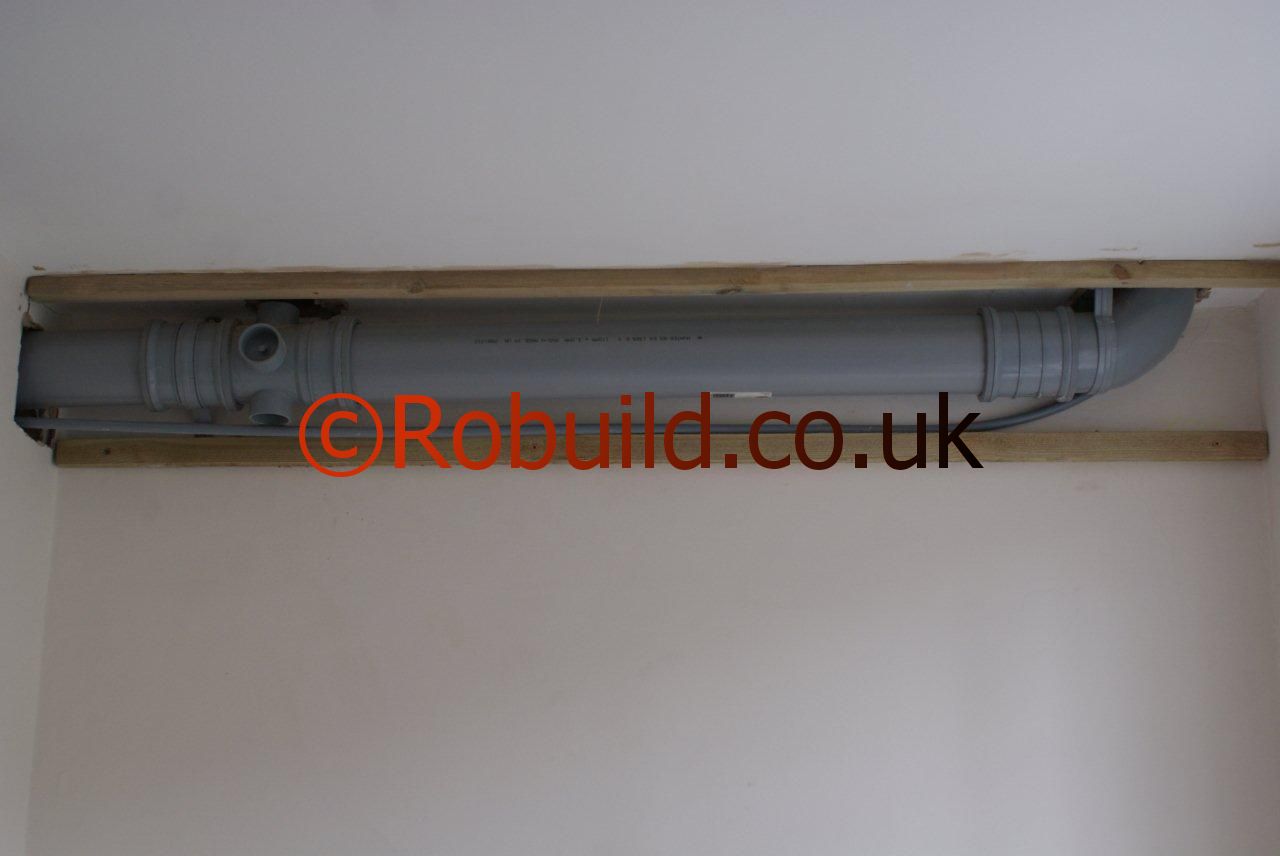
plastic pipe drain bathroom
Socketed pipes or a special separate fitting, are used with this method. First ensure that the surfaces to be welded are completely clean and grease free. Manufacturers usually supply a special cleaner for this. Then coat the two surfaces thoroughly with the special solvent cement. Note that you should always use the solvent recommended by the manufacturers as some solvents are not suitable for particular plastics. When both surfaces have been coated all that remains is to insert the spigot end of the pipe into the socket of the other or into the special fitting as far as it will go (a ‘stop’ is provided to prevent you pushing it too far). Then give the pipes or pipe and fitting a twist to distribute the solvent evenly. Wipe off any excess solvent squeezed out of, the joint and leave the joint for between 12 and 24 hours (according to the manufacturer’s recommendations) before testing.

The advantage that rubber ring-sealed joints have over other methods is that allowance is made within each joint for thermal expansion. With this joint an ‘O’ or ‘D’ shaped rubber ring is first inserted into a groove in the socket end of one pipe (or into a separate fitting). A special lubricant – soap can be used if the manufacturer does not supply one-is smeared over the spigot end of the pipe and the pipe is then pushed firmly into the socket or fitting as far as it will go. It is particularly important to ensure that the rubber ring does not become displaced during fitting, so the two pipes must be perfectly in line during this operation. Note that the end of the spigot should be chamfered to about 15 degrees for easy insertion.

This chamfer is normally included in the spigot end during manufacture, but if you have to cut the pipe use a file to chamfer the cut end. When you have pushed the pipe right up to the stop, withdraw the pipe a certain distance to allow for an expansion gap. This gap varies according to the material used. Some manufacturers put a mark on the pipe near the end and others give instructions as to how far to withdraw the pipe.

Installation details

The manufacturer’s instructions regarding the installation of their pipework should be closely studied and followed exactly. The main factor to take into account is thermal movement. If your pipes are jointed with the ring seal method you have no problems as allowance is made, as described above, for expansion in every joint. You must still, however, be careful that no tight restrictions are placed on the pipes themselves. Pipe clips (spaced at manufacturer’s recommended intervals) must not be so tight as to restrict the expansion of the pipe. You must also leave suitable gaps wherever pipes pass through walls.

The solvent welding method of jointing, however, prevents any movement in the joints and allowance has to be made elsewhere in the system. This is done by incorporating special expansion couplings at specified distances apart. Providing you take particular care to read all instructions thoroughly the actual physical work involved in installing a plastic pipework system is quite straightforward and easy, and you will have a system that should be maintenance free and exceptionally long lasting.

South Kensington

Boilers, Central Heating, Drains,Plumbing

We have a very professional team of Gas Engineers and Plumbers,fully qualified and Gas Safe Registered plumbing team.
New boiler installation, boiler repairs,combi boilers, central heating,radiators, underfloor heating,showers, bathrooms,kitchens, gas work,drains.
We cover South Kensington & Chelsea.

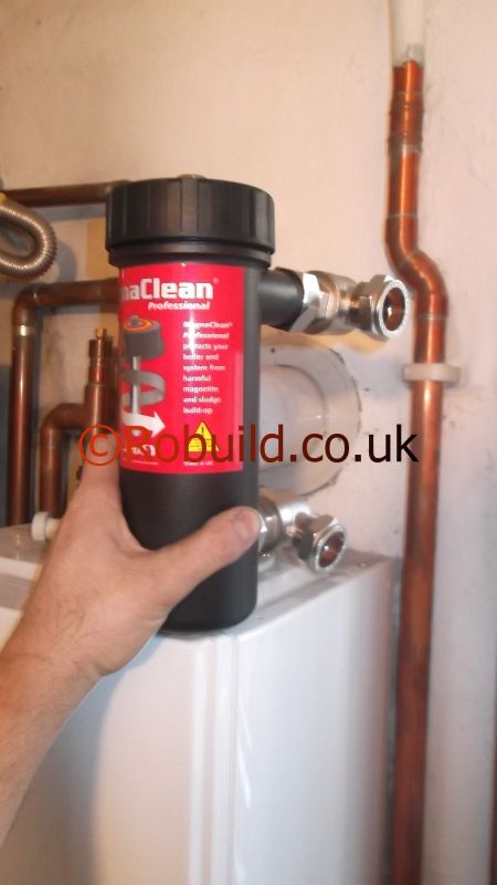
central heating boiler

Capillary fittings

More work is involved when making joints with this type of fitting, but they have the advantage of being cheaper and less bulky than compression fittings. There are two types: one has a ring or reservoir of solder incorporated during the manufacturing process and simply needs the application of heat to seal the joint ; the other type, known as ‘end feed’, has to have molten solder introduced at the fitting mouth.

capillary fittings plumbing pipes

Before you start to make the joint, make sure that the surrounding area will not catch fire when you use the blow torch. Use asbestos mats (if you do not have them, spare pieces of ceramic tile will do) to cover any adjacent material liable to catch fire. To make a capillary joint, alter cutting and preparing the pipe, thoroughly clean the inside of the fitting and the surfaces of the pipes, otherwise the solder will not adhere. Use a rag to remove any grease or dirt and then burnish them to a bright finish with either fine wire wool or fine glasspaper.

A suitable flux recommended by the fitting manufacturer should then be smeared over the outside of the pipes and the inside of the fitting. Take care that no areas are left bare. Now insert the ends of the pipes into the fitting, ensuring that they reach the integral stop, and make a scratch mark on the pipes next to the fitting to indicate any unwanted movement. Either the fitting or the pipes should then be twisted to help ‘bed in’ and distribute the flux evenly. Wipe off any excess left outside the joint. Heat should now be evenly applied to the whole fitting area with the blow torch.

With pre-soldering fittings it is only necessary to continue heating until a ring of solder appears around the circumference of the fitting mouth. While not strictly necessary, an added precaution against leaking is to run a piece of cored solder around the mouth of the still-hot joint. End-feed fittings should be heated until they are sufficiently hot to melt the solder wire, which is introduced around the mouth of the fitting. Once the solder starts to melt, slowly take it round the fitting mouth until the fitting overflows and will accept no more. Leave a ring of solder around the edge of the fitting as before.

Once the joint has been completed, using either fitting, leave it for at least two minutes to cool and harden. Finally wipe off any flux left on the exterior of the joint. If you are using stainless-steel pipe, special precautions must be taken to make a satisfactory joint. Ordinary flux used for copper is not satisfactory; an ‘aggressive’ flux is necessary to remove the oxide which forms more quickly on stainless steel than on other metals. Several types of flux, in liquid and paste form, are suitable, most of which contain an acid base. As these are highly corrosive, they should be handled with care, and any excess left on the external surface of the pipes and fittings ,must be removed.

The pipes should also be flushed out as soon as possible to remove any traces of flux from the inside of the pipe bore. The other difference concerns the application of heat. This should be directed on the fitting only, and not on the pipes. This is because the thermal conductivity of stainless steel is lower than copper and any heat applied to the pipe will not be effective.

Compression fittings

Compression fittings are the most common type and the easiest to use. Two types are available :’manipulative’ and ‘non-manipulative’. The first is seldom used nowadays for domestic purposes. A special tool is required to ‘bell out’, or force open, the ends of the pipes, which are then compressed against the fitting body, when the nuts are tightened, to make the joint.

Non-manipulative fittings rely on the compression of a soft metal ring, known as a cone, olive or ferrule, against the external wall of the pipe to create the joint between pipe and fitting. No ‘working’ or distortion of the pipe itself is required, and so the work involved is much easier. To make a joint with this fitting, the pipe ends must first be cleaned up, as previously described, with the files. Place the nuts on to the pipes, and then the cones. The cones have two chamfered faces, and if one of these is longer than the other, the long face must be placed towards the pipe end. Each pipe is then inserted into the fitting as far as it will go. A ‘stop’ moulded into the fitting will determine the depth of entry.

You must ensure that the pipes do not ‘creep’ out of the fitting while the joint is being made. Once they have been pushed in, scratch them next to the fitting with a nail or other sharp object. This will show up any movement. Before sliding home the cones, it is wise lo srnear a little non-toxic jointing compound on the cone. Manufacturers do not stipulate this, but it helps to ensure a watertight join. Once the cones are inserted into the fitting, the nuts should be engaged on the threads and tightened as far as possible by hand. Two or three turns with an adjustable spanner on each nut are generally sufficient to complete the union. Use the second spanner to hold the body of the fitting while you tighten each nut. Do not overtighten or either the threads may strip or the olive may be forced into the pipe, making a bad joint. Although the procedure described above is basically the same for all makes of nonmanipulative fittings, it is wise to read any instructions supplied by the manufacturer before starting work.

Connectors and fittings

An extensive range of fittings is available for joining pipes together and for connecting them to taps, cisterns and so on. Straight connectors, bends and tee junctions are most commonly used for joining pipes. In addition to these there are ‘tap’ connectors designed for fitting to male iron threads (taps and ball valves), ‘tank’ connectors which have two flanged surfaces for attaching to the side of a water storage cistern, and various adaptors for changing from iron or lead pipe to copper or stainless steel.

Fittings are also available which are designed to permit a reduction in pipe bore. Other, not so common ones, include drain-off cocks, stop ends, blanking off discs, swept tees, and obtuse bends. This is not a complete list of available fittings. Manufacturers issue catalogues of their fitting range and it is well worth acquiring a copy for reference purposes. For joining copper or stainless-steel pipe, two types of fitting can be used-compression and capillary

Bending copper pipes

Using bending springs is a simple job which requires little practice to achieve successful results. The spring should be inserted into the pipe so that the middle of the spring roughly corresponds with the proposed bend point. If this means that the spring will disappear into the pipe, attach a length of nylon cord or thick string to help you remove it after the bend has been made. In many cases the easiest way to make the bend is to place the pipe, with the spring inserted, just below your kneecap and, holding it either side, gently pull it towards you.

As it is difficult to correct a greatly overbent pipe by this method, first underbend and then check the angle before proceeding. If the pipe proves too tough to bend this way, obtain a thick piece of wood, about l00mm x 50mm and about 610 mm long, and drill a hole near one end slightly larger than the diameter of the pipe. Chamfer the lower edges of this hole with a suitable tool (the round file will do). Then place the bottom of the wood on,the floor or workbench, insert the pipe in the hole, and then press down on either side. When the bend has been completed, the spring is sometimes difficult to withdraw. This can be overcome in two ways. The first is to insert a screwdriver through the eye at the top of the spring and unscrew it anti-clockwise. The other method is to overbend the pipe slightly, then correct. This loosens the ‘grip’and the spring can then be pulled out.

How to cut copper pipe

If you are using a vice to hold the pipe steady, wrap a thick piece of cloth around the pipe to protect it from damage. Another method is to hold the pipe on top of your left foot (if you are right handed) to steady it while cutting. This method enables you to cut the pipe where you are working and so avoids frequent journeys to the workbench. But you need a straight eye ! When using the hacksaw, use only gentle and even pressure and take care to make a straight cut-a crooked one will impede good joint making later. Stainless-steel pipes are much tougher than copper and more pressure is needed to cut them with a hacksaw. A pipe cutter has the advantage of producing a straight, clean cut more easily than a hacksaw.

A typical one has three toughened metal .wheels mounted on a frame to form a triangle. The circumference of each is tapered to form a cutting edge and a threaded spindle is attached to one of the wheels for adjustment. To cut the pipe, insert it between the wheels and position them over the cutting point. Adjust the cutters so that they grip and turn the tool a couple of times round the pipe. Then tighten the spindle to deepen the cut and continue turning, re-tightening as you go, until the pipe is severed. Once the cut has been made, the burrs, or jagged edges, left inside and outside the pipe end must be removed. If they are left, they can restrict the water flow and create unwanted turbulence within the pipe. They can also make the actual jointing of the pipes much more difficult, if not impossible, particularly where capillary fittings are used. To remove them, use the flat file to clean off the external edge, and the round file for the inside. Many pipe cutters have an accessory for this. Also bevel the outside edges of the pipe slightly with the flat file as this will enable the pipe to fit tightly inside the fitting.

Lagging

Insulating the loft door is effective, but in cold climates it makes the loft itself very cold indeed. Little of the the heat used to penetrate can now do so. If the cold water cistern is up there, as it is in most British houses, you will have to lag it , wrap it up to stop it freezing in the winter. Leave a space in the floor insulation under the cistern so that a little heat reaches it from below.

The cistern itself can be lagged with various materials. A special type of fibreglass blanket is sold for the purpose. There are tank lagging kits available that use cut-to size insulation boards to fit all standard sizes of cistern. The boards fasten together with clips that are supplied with the kit. Holes can be cut for the cistern’s pipes with a handyman’s knife.

Measure the exact position of the hole from the two nearest edges with a ruler. Cut as small and neat a hole as possible, and cut out a strip of board from the hole to the edge of the board so that you can slide the board into place over the pipe. When the board is in position, put the strip back and clip it down. Join the edges of the floor insulation to the sides of the tank insulation so that no heat seeps through the gap.

Heat insulation

There is a tendency among builders to skimp on the insulation that they should be installing in every new house, but you can remedy this in your own home at a cost of a few pounds. Proper heat insulation is a ‘must’ in any climate from the Arctic to the tropics-in cold weather it keeps the interior of the house warm, and in hot weather it keeps it cool. If you live in an average British semidetached house with central heating you may be wasting as much as three-quarters of your fuel in heating the air outside your house. It has been estimated that in a house of this type, only 25 % of the heat produced goes to heat the rooms. Of the rest of the heat, 25% goes through the outside walls, 20& through the roof, 20% through windows, doors and chimneys, and 10% through the ground floor. In a terrace house, slightly less heat is wasted than this, and in a detached one, slightly more. In a modern house with large windows, even more heat may be lost.

In any case the annual waste of money is enormous. In a hot climate, of course, the problem is quite the reverse -to stop the sun that beats down on the roof from making the house interior too hot. In some countries. there has been a trend since the Second World War to make roof pitches (slopes) lower and lower sometimes as little as l6 degrees. This reduces the volume of air available as ‘insulation’ between roof and ceiling, and helps make the running of an air conditioning system more expensive than it would otherwise be. The answer to both problems is efficient insulation. Insulating a house properly can reduce heating bills by 35% while keeping the rooms at the same temperature, or can make the house much warmer without using more fuel. Similarly, insulation can reduce substantially the power consumption of an air conditioning system,or, in a moderately warm climate, even make one unnecessary. The greatest fuel savings made by insulation are in houses with central heating. Provided the insulation is done economically, it should pay for it self in two years’ saving on fuel bills. In houses with local heating, such as electric fireplaces or gas fires, people tend to heat only the rooms they use most, and the saving is not so great. But insulation will still make the house more comfortable. Many postwar British houses have a certain amount of insulating material already installed. But standards are not very high as a rule, and adding more insulation is generally worthwhile.

Value for money
An important factor in deciding whether insulation is worthwhile or not is, of course, the cost of installing it. For example, salesmen of double glazing windows and doors often clainr that their glazing halves the heat loss through windows. This sounds impressive until you realise what a small proportion of the total area of a house the windows occupy. Halving the heat loss through them might reduce heating bills by cornparatively little. If this is the case, then obviously it would be better to spend the money elsewhere. Before installing one type ol insulation rather than another, it is a good idea to find out the relative costs ol various n-rethods of insulation, and how ellcient they are. The efficiency of an insulating material is expressed as a’U value’, and the brochures put out by insulating-material manufacturers generally state the improvement in U value obtained by using their material.

U value measures the amount of heat that passes through a material in a given time, so a high U value is undesirable and a low U value is desirable. For example, a properly-insulated lolt floor may have a U value as low as 0.08. If it is not insulated at all, the U value averages 0.43 in post-war houses. The U values quoted by manufacturers for their products are average figures for houses in normal positions. If your house is in a very exposed position, such as on a hill or overlooking the sea, the U value of even the best insulation will be raised, and therefore worsened, by the winds whistling around your roof and walls. You will need more and better insulation. Similarly, if your house is in a sheltered valley and surrounded by trees, you will not need so much insulation to keep it warm-though in fact the more insulation you have, the more heat you save.

Toilet of the future

‘Toilet of the future’ solves global issues

Last summer, Hoffmann, the James Irvine Professor of Environmental Science at Caltech, and his team were awarded a $400,000 grant to create a toilet that can safely dispose of human waste for just five cents per user per day. The lavatory can’t use a septic system or an outside water source, or produce pollutants.

The challenge is part of a $40 million program initiated by the Gates Foundation to tackle the problems of water, sanitation, and hygiene throughout the developing world. According to the World Health Organization, 2.5 billion people around the globe are without access to sanitary toilets, which results in the spread of deadly diseases. Every year, 1.5 million people—mostly those under the age of five—die from diarrhea.

Hoffmann’s proposal—which won one of the eight grants given—was to build a toilet that uses the sun to power an electrochemical reactor. The reactor breaks down water and human waste into fertilizer and hydrogen, which can be stored in hydrogen fuel cells as energy. The treated water can then be reused to flush the toilet or for irrigation.